Definition:
A logic gate is a fundamental logical construct that performs a basic Boolean operation—such as AND, OR, or NOT—on one or more binary inputs to produce a single binary output. Logic gates are not limited to hardware or logic solvers; they represent the underlying Boolean logic used throughout the functional safety life-cycle.
In functional safety, Boolean logic appears in many forms: during hazard and risk assessment when conditions are combined, within SIF architecture where MooN arrangements represent logical relationships, in application program development (the primary one people think about), and during testing and validation when expected outcomes are verified against input conditions.
Key Points:
- Logic gates operate on binary inputs (true/false, 1/0) to produce a binary output.
- Gates can exist as conceptual logic, not just as software or hardware elements.
- Gates may have more than two inputs, although two-input gates are the most common.
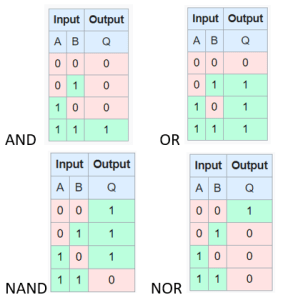
- For two-input logic, there are 16 possible logic gate types.
- The most commonly encountered gates in functional safety are AND, OR, NAND, and NOR.
- Boolean logic is used across hazard analysis, SIF architecture, program design, and validation testing.
Example:
A SIF requires two pressure transmitters in 2oo3 to detect high pressure before a shutdown occurs. In the application program an AND gate is used so that both inputs must be true before the trip output is activated. Alternatively, a NAND or NOR gate may be used depending on fail-safe design philosophy and how loss of signal or diagnostics are handled.
This figure shows the outputs of a four most common gates. There are 16 total two-input logic gates
See Also: logic diagram
Other Sources:
- See logic.ly which is an excellent and simple software package