A piping and instrumentation diagram, or P&ID, is the detailed drawing that shows every piece of equipment, pipe, valve, and instrument in a process, along with how they all connect. If the process flow diagram is the overview, the P&ID is the working document the plant actually runs, maintains, and modifies from. It carries tag numbers, line sizes, instrument loops, control and shutdown valves, and interlock references. You will also see it written without the ampersand, simply as PIDs, but it is the same drawing either way.
For functional safety the P&ID is the single most important reference drawing. It is where we trace each safety instrumented function, identify the sensors, logic solver, and final elements, and check that the trips shown on the drawing match the safety requirements specification. A HAZOP is run node by node straight off the P&IDs, so a sloppy or out-of-date P&ID quietly undermines the entire hazard study.
Key Points
- Shows all equipment, piping, valves, and instrumentation with tag numbers, unlike the higher-level PFD.
- The primary working drawing for HAZOP, SIF design, and management of change.
- Instrument and valve symbology generally follows the most excellent ISA-5.1.
- Keeping P&IDs current is an asset integrity issue, an out-of-date P&ID misleads every downstream review.
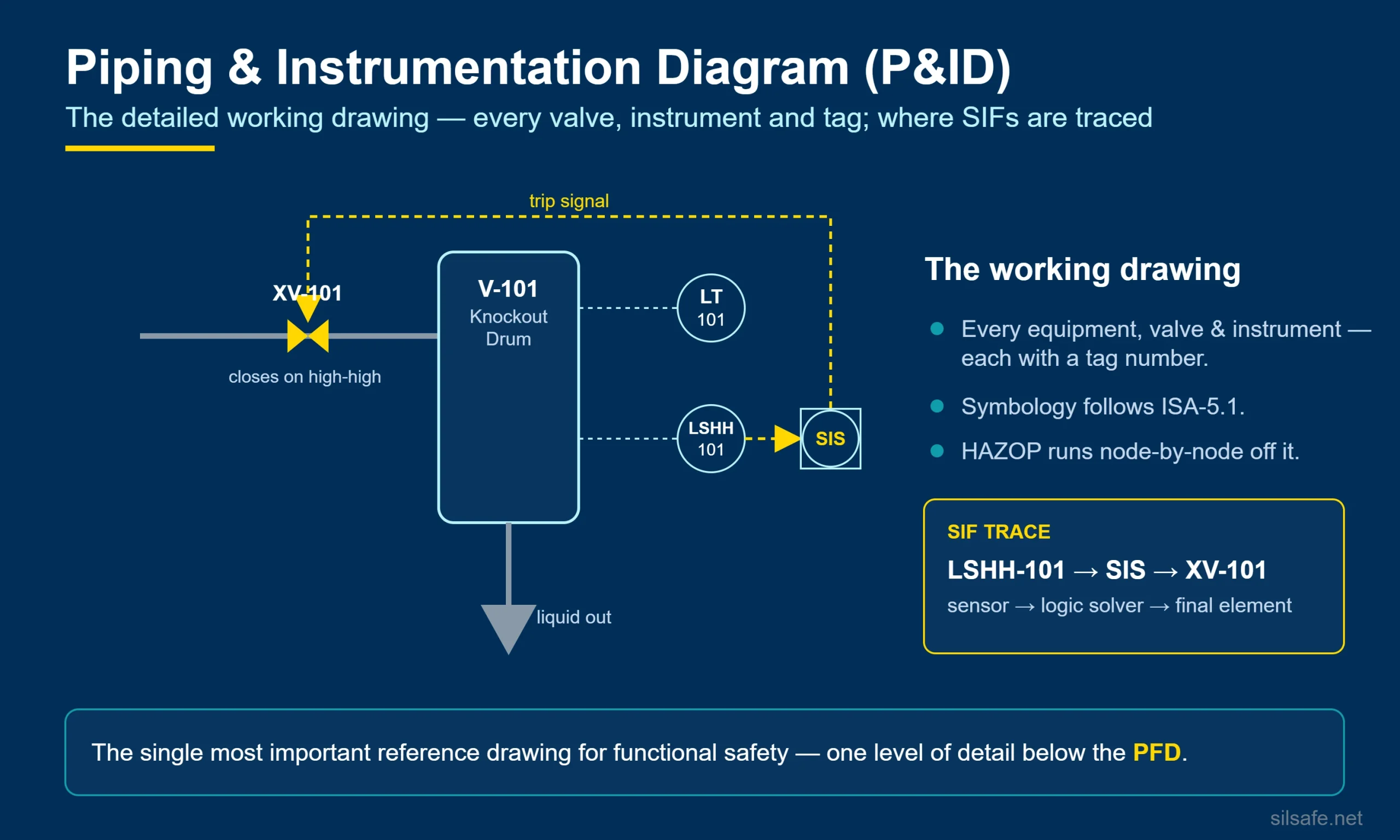
Example
On a P&ID for a knockout drum you would see the level transmitter LT-101, the high-high level switch LSHH-101, the logic solver reference, and the shutdown valve XV-101 that closes on high-high level, with the interlock number noted beside it.
See Also: process flow diagram, logic diagrams
Cited Sources
- ISA-5.1-2009 (R2022), Instrumentation Symbols and Identification, the standard governing the instrument and valve symbology used on P&IDs.