A process flow diagram, or PFD, is the high-level drawing that shows how a process works at a glance. It lays out the major equipment, the main process streams, and the key flows, temperatures, pressures, and material balances, without getting into every valve, instrument, or line. Think of it as the 30,000-foot view of the plant: where the feed comes in, what the big vessels and pumps do, and where product leaves. It is often the first major step in a design process and an early draft is often done pre-contract.
For functional safety work we usually start at the PFD to understand a process before diving into the P&ID. One word of caution: in our world the letters PFD are overloaded. On a drawing PFD means process flow diagram, but in a SIL calculation PFD means probability of failure on demand. Context tells you which one is meant, but it trips up newcomers constantly.
Key Points
- Shows major equipment, primary streams, and the overall material and energy balance, not individual instruments.
- Sits one level above the P&ID in the drawing hierarchy and one level below the block flow diagram.
- A clear PFD is the natural starting point for a HAZOP or other process hazard analysis.
- The acronym PFD also means probability of failure on demand in SIL math, so always read it in context.
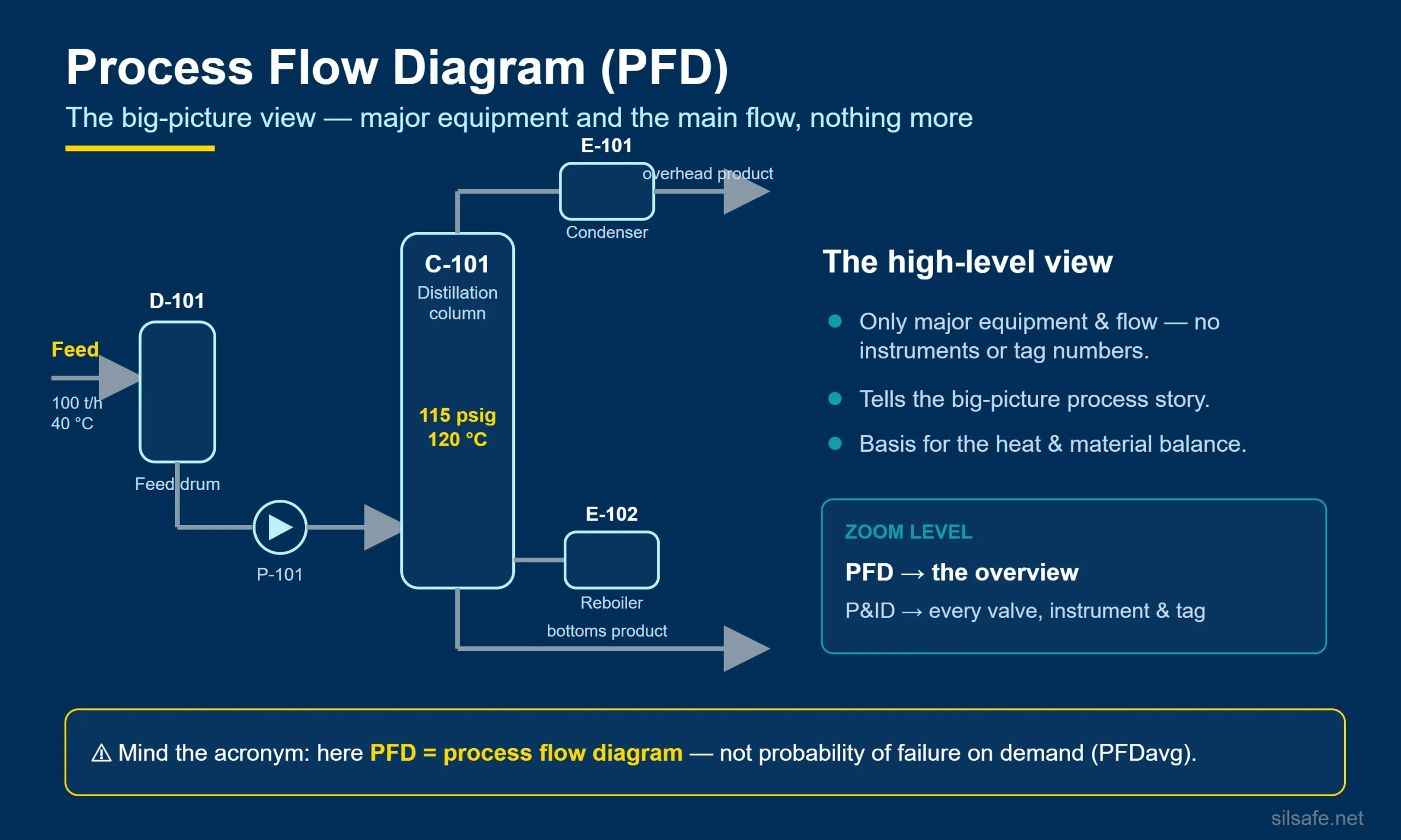
Example
A PFD for a distillation unit shows the feed drum, the column, the reboiler, the condenser, and the product pumps, with stream flow rates and the column operating pressure and temperature called out. It does not show the level transmitters, control valves, or trip logic. Those live on the P&ID.
See Also: P&ID, logic diagrams
Cited Sources
- ISO 10628-1:2014, Diagrams for the chemical and petrochemical industry — Part 1: Specification of diagrams, the international standard that classifies block, process flow, and P&ID drawings.
- AIChE tutorial: Block Flow, Process Flow, and Piping & Instrumentation Diagrams — a free, practical overview of how the three drawings relate.