In the process industry, determining how much risk reduction a safety instrumented system (SIS) needs to provide is one of the most consequential decisions in SIS design. Layer of protection analysis, or LOPA, is the method most facilities use to make that determination. It is the most widely used safety integrity level (SIL) selection method in the process industry, and this article explains how it works, where it fits in the IEC 61511 safety life-cycle, and what it looks like applied to real scenarios at a natural gas processing facility.
LOPA can be conducted as a semi-quantitative or quantitative analysis. The vast majority of LOPA studies — roughly 80% — are semi-quantitative.
LOPA Key Terms
These terms appear throughout every LOPA study.
Initiating event — the specific failure or error that starts the hazard sequence, such as a pump trip, a valve failing open, or an operator error.
Independent protection layer (IPL) — a safeguard capable of preventing the hazard from escalating to a consequence, provided it meets all four criteria: specific, independent, dependable, and auditable.
Risk reduction factor (RRF) — a measure of how much a protection layer reduces risk. An IPL with an RRF of 100 prevents the hazardous outcome on 99 out of 100 demands. RRF and probability of failure on demand (PFDavg) are inverses: RRF = 1 / PFDavg.
Tolerable risk — the maximum frequency of a hazardous event the facility has determined is acceptable. LOPA compares mitigated event frequency against this threshold.
Additional terms specific to quantitative LOPA are introduced later in this article.
How a LOPA Scenario Works
LOPA determines how much risk reduction is needed for each specific hazard scenario — not a facility-wide number. Each scenario is analyzed individually, which is what makes LOPA more rigorous than a risk graph or qualitative approach. The structure is simple: one initiating event, one consequence. That narrow scope is intentional.
The core equation is:
Mitigated Event Frequency = Initiating Event Frequency × (PFD of IPL-1) × (PFD of IPL-2) × … × modifiers
The mitigated event frequency is compared to the facility’s tolerable risk threshold. If the mitigated frequency falls below the target, no additional protection is needed. If a gap remains, the required RRF is calculated and a SIL target assigned to close it. LOPA establishes the target — it does not calculate whether the SIS design achieves it. That is the job of SIL verification, which comes later in the life-cycle.
LOPA was formalized by the Center for Chemical Process Safety (CCPS) in their 2001 book Layer of Protection Analysis: Simplified Process Risk Assessment. IEC 61511-3, Annex F (informative) incorporates it as a recognized semi-quantitative method within the standard.
Initiating Events
Before evaluating whether safeguards are sufficient, a credible frequency for the initiating event is needed. Typical frequencies used in semi-quantitative LOPA:
- Control valve fails open or closed: 1E-1 per year
- Pump trip (loss of flow): 1E-1 per year
- Operator error on a routine task: 1E-2 per year
- Cooling water failure: 1E-1 per year
- Small bore pipe rupture: 1E-3 per year
These are starting points. Facility-specific data and operating history should inform what is reasonable for a given site.
One important point: the basic process control system (BPCS) can itself be the initiating event. If a BPCS pressure control loop failure causes an overpressure scenario, that same loop cannot be claimed as an IPL for that scenario — it is not independent of the cause.
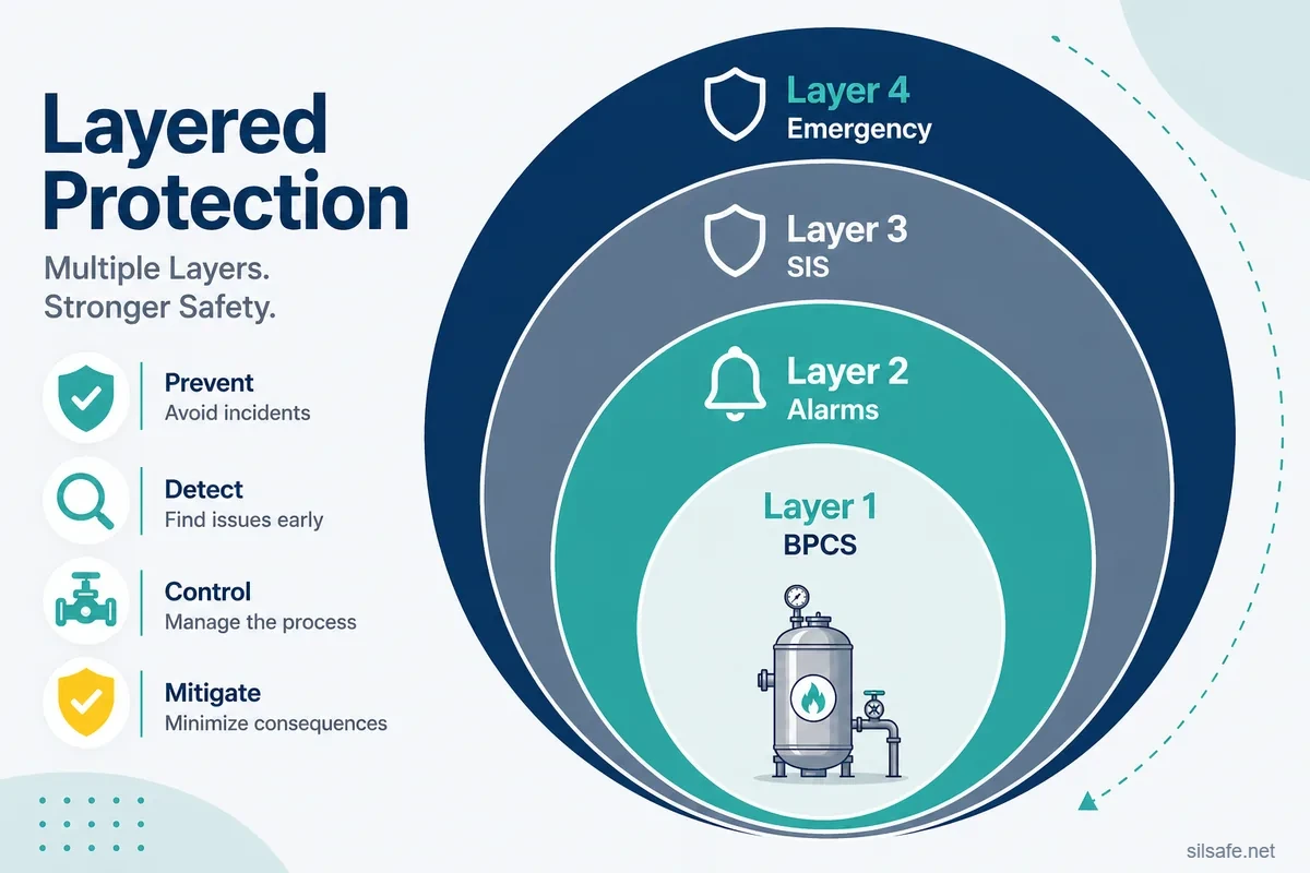
Independent Protection Layers (IPLs)
To qualify as an IPL, a safeguard must satisfy all four criteria — and all four means all four:
- Specific — capable of preventing the specific consequence being analyzed
- Independent — functions independently of the initiating event and of other IPLs claimed in the same scenario
- Dependable — performs with the reliability assumed in the analysis
- Auditable — supported by documentation proving it exists, works, and is maintained
Common IPL types and typical risk reduction credit in semi-quantitative LOPA:
- BPCS control loop: RRF of 10
- Operator response to alarm: RRF of 10, with sufficient response time and documented procedures
- Pressure safety valve (PSV): RRF of 10 to 100, depending on sizing and testing for the specific scenario
- Safety instrumented function (SIF): RRF varies by SIL — this is what LOPA is sizing
The BPCS as an IPL: why RRF 10 is the limit
The cap of RRF 10 for a BPCS loop is based on real-world data. A control loop has many ways to fail beyond the primary sensing element — control valve degradation, signal wiring faults, software changes, maintenance errors, the loop being placed in manual. When all failure modes across the full loop are accounted for, historical plant data consistently supports an RRF of 10 as a reasonable and defensible credit. Claiming more is not supported by what facilities actually see in the field.
What disqualifies a safeguard
- A high-level alarm tied to the same transmitter as the control loop that caused the initiating event — fails independence
- A spare pump with no documented proof test procedure — fails dependability and auditability
- An operator response procedure requiring 45 minutes when the scenario allows 20 minutes — fails specificity
Enabling Conditions and Conditional Modifiers
Enabling conditions and conditional modifiers can legitimately reduce the calculated demand frequency or consequence likelihood in a LOPA scenario. An enabling condition is something that must be present for the consequence to occur but does not itself cause the initiating event — the presence of an ignition source, or a person in the hazard zone. A conditional modifier is a probability factor applied to account for conditions that affect whether the initiating event leads to the full consequence, such as probability of ignition or occupancy probability.
In semi-quantitative LOPA, these are typically embedded in the initiating event frequency or handled with conservative round numbers. The risk of abuse is real: stacking multiple modifiers without documented evidence produces an analysis that is optimistic rather than conservative.
Semi-Quantitative vs. Quantitative LOPA
Semi-quantitative LOPA uses order-of-magnitude estimates for initiating event frequencies and IPL PFD values, drawn from standardized tables rather than facility-specific reliability data. It is conservative by design and appropriate for the data quality available at most facilities.
Quantitative LOPA assigns precise numerical values to each input and applies conditional modifiers explicitly as documented multipliers. The following terms are specific to quantitative LOPA and are unlikely to appear on a standard semi-quantitative worksheet:
- Implicit vs. explicit modifiers — a modifier is implicit when its effect is already embedded in the source data; explicit when it is a named, separate multiplier on the worksheet
- Operational factor — the fraction of time the process is running in the hazardous state (e.g., a unit running 6 months per year applies a factor of 0.5 to the initiating event frequency)
- Use factor / occupancy factor — the fraction of time a person is present in the hazard zone, used to probability-weight a consequence
Mixing the two approaches is a common mistake — applying precise numerical modifiers in an otherwise semi-quantitative study creates false precision and can produce unconservative results. A future article will cover quantitative LOPA in depth.
Where LOPA Fits in the IEC 61511 Safety Life-Cycle
IEC 61511 requires a documented, defensible basis for every SIL target. Layer of protection analysis is how most facilities satisfy that requirement. The standard does not mandate LOPA specifically — several methods are acceptable — but LOPA dominates in practice.
Note that where LOPA sits can confuse practitioners as it is at the boundary between two phases of the IEC 61511 life-cycle. The scenario evaluation, IPL crediting, and risk gap calculation are Clause 8 risk H&RA (specifically on the “A” side), while the resulting required risk reduction is consumed by Clause 9 when that risk reduction is allocated to a SIF and the SIL is assigned.
What Comes Before: The “H” of the H&RA
The hazard and risk assessment (H&RA) is a mandatory IEC 61511 life-cycle activity. The HAZOP (Hazard and Operability Study) is the most common method used to carry it out the “H” portion. The term process hazard analysis (PHA) refers to the same concept in OSHA PSM and EPA RMP contexts. The H&RA identifies hazard scenarios, defines consequences, and establishes unmitigated risk. LOPA does not re-identify hazards (the “H” term); it takes the HAZOP output and determines whether existing protection is sufficient.
HAZOP and LOPA are often conducted together in the same study or meeting, and some facilities call the entire exercise a “HAZOP” even when LOPA is embedded within it. If a study only lists safeguards without comparing them to a tolerable risk threshold, it is a HAZOP — not a LOPA, regardless of what it was called.
What Comes After: SIS Design Begins
The SIL target produced by LOPA is the starting point for SIS design. From there, engineers move into the full design process — developing the safety requirements specification (SRS), working through conceptual and detailed design, selecting equipment, performing SIL verification, and ultimately installing and validating the system. PFDavg calculations, spurious trip rate (STR) analysis, proof test interval (TI) optimization, and common cause failure (CCF) evaluation are all part of that design and verification work. LOPA hands off a SIL target; everything that follows is about proving the design meets it.
A note on ALARP: LOPA establishes the minimum required risk reduction. As low as reasonably practicable (ALARP) is a separate obligation that asks whether risk can be reduced further at a reasonable cost — it is not a basis for doing less than LOPA requires. Facilities subject to ALARP obligations should treat LOPA output as the starting point, not the conclusion.
Other SIL Selection Methods — and Why LOPA Dominates
IEC 61511 accepts several SIL selection methods. The right choice depends on the facility, available data, and scenario complexity.
Risk graph — a parameter-based method that works through structured questions about consequence severity, occupancy, avoidability, and demand rate to arrive at a SIL target. Used in some sectors and regulatory contexts; works well when properly calibrated to the facility’s risk tolerance.
Fault tree analysis (FTA) / quantitative risk analysis (QRA) — the most rigorous end of the spectrum. Appropriate when consequence modeling is required (toxic dispersion, blast overpressure) or when regulatory requirements demand precise probabilistic treatment.
LOPA dominates because it fills the practical gap between a qualitative approach and a full QRA — rigorous enough to be defensible, practical enough to execute without a specialized modeling team. That said, a risk graph may serve better when a facility has built its procedure around one and knows how to use it well, and a full QRA may be necessary when consequence modeling is non-negotiable.
LOPA in Practice — Two Examples
Setting the Scene
The facility is a mid-size natural gas processing plant subject to OSHA PSM. It processes raw natural gas to remove liquids, water, and acid gases (H₂S and CO₂) before pipeline delivery. Both examples are set in the amine treating unit — a section of the plant that uses a liquid amine solution to absorb H₂S from the gas stream through direct gas-liquid contact.
The facility’s tolerable risk criteria:
- Potential single fatality: 1E-4 per year
- Potential multiple fatalities: 1E-5 per year
Example 1: Existing Safeguards Are Sufficient — No SIF Required
Scenario
The gas-liquid contact vessel in the amine treating unit operates at elevated pressure. A control valve failing open on the high-pressure gas inlet could allow pressure to build beyond the normal operating range, leading to a flange leak or seal failure and H₂S release near the unit. Consequence: potential single fatality.
Initiating event: Control valve fails open — 1E-1 per year
Tolerable risk target: 1E-4 per year (single fatality)
Required RRF before IPLs: 1E-1 / 1E-4 = 1,000
IPL evaluation
IPL 1 — BPCS pressure control loop The BPCS loop is independent of the failed inlet valve. Functional, tested, and documented. Credit: RRF = 10
IPL 2 — High-pressure alarm with operator response The alarm activates at 110% of normal operating pressure on a separate transmitter. The operator has a documented response procedure and approximately 25 minutes to respond before a credible consequence — sufficient for trained response. Credit: RRF = 10
IPL 3 — Pressure safety valve The PSV is sized for the credible overpressure load from this specific scenario, including the valve fail-open case. Bench tested annually with documentation on file. Credit: RRF = 100
Mitigated event frequency
1E-1 × (1/10) × (1/10) × (1/100) = 1E-5 per year
Achieved RRF = 1E-1 / 1E-5 = 10,000
Result: The mitigated event frequency of 1E-5 per year is below the tolerable risk target of 1E-4 per year for a single fatality event. No SIF is required.
Example 2: Existing Safeguards Fall Short — SIL 2 SIF Required
Scenario
The amine regenerator column — the vessel that thermally strips H₂S from the amine solution for reuse — operates at elevated temperature. Loss of cooling water to the overhead condenser allows column pressure to rise. If pressure exceeds the column design rating, a catastrophic release of hot amine and H₂S-bearing vapor is possible. Consequence: potential multiple fatalities.
Initiating event: Cooling water failure — 1E-2 per year
Tolerable risk target: 1E-5 per year (multiple fatalities)
Required RRF before IPLs: 1E-2 / 1E-5 = 1,000
IPL evaluation
IPL 1 — BPCS pressure control loop The BPCS loop is independent of the cooling water failure. Functional, tested, and documented. Credit: RRF = 10
Candidate IPL — High-pressure alarm with operator response A high-pressure alarm is present. However, the response procedure requires approximately 18 minutes to complete, and the time available from alarm to potential consequence — based on process dynamics — is 12 minutes. The response time does not fit the scenario. This safeguard does not qualify as an IPL.
Candidate IPL — Pressure safety valve A PSV is installed on the column but was sized for a blocked outlet case. Documentation confirming adequacy for the loss-of-cooling scenario is not available. This safeguard does not qualify as an IPL for this scenario as evaluated.
Mitigated event frequency
1E-2 × (1/10) = 1E-3 per year
Achieved RRF = 1E-2 / 1E-3 = 10
Gap analysis
Required RRF: 1,000 | Achieved RRF: 10 | Remaining gap: RRF of 100
An RRF of 100 falls within the SIL 2 range (RRF 100 to 1,000). A SIL 2 SIF is required.
Result: The mitigated event frequency of 1E-3 per year does not meet the tolerable risk target of 1E-5 per year for a multiple fatality event. Existing safeguards are insufficient. The LOPA identifies a SIL 2 SIF as the minimum required protection layer.
This example also surfaces two recommendations: confirm whether the operator response procedure can be shortened — if the time gap closes, that safeguard may qualify as an IPL and reduce the SIL requirement. And confirm PSV sizing for this specific relief scenario — if adequate, it may also qualify as an IPL.
Common LOPA Mistakes
Claiming IPL credit for untested or undocumented safeguards. If there is no proof test record and no written procedure, the safeguard fails the auditable criterion. No documentation means no credit, regardless of whether the safeguard is functioning.
Double-counting BPCS-based safeguards. A BPCS pressure control loop and a BPCS high-pressure alarm on the same transmitter are not two independent IPLs. Independence means independence all the way through — sensing element, signal path, and control action.
Misidentifying available operator response time. Response time in LOPA is the window between alarm activation and the point at which the consequence becomes unavoidable — not the total time available to complete a recovery procedure, and not the time from process deviation to alarm.
Failing to evaluate IPL validity for each initiating event independently. An IPL that qualifies for one scenario may not qualify for another — this check must be done scenario by scenario, not at the system level. More critically, an IPL’s own failure mode can itself become an initiating event on a different accident path, a cross-scenario interaction that is easy to miss.
Mixing semi-quantitative and quantitative practices. Applying precise numerical modifiers — occupancy factors, operational factors — in an otherwise semi-quantitative study creates false precision. If the data doesn’t support the specificity, the result can be unconservative.
Not revisiting LOPA when the process changes. This is fundamentally a management of change (MOC) failure. Changes to operating conditions, throughput, equipment, or chemicals can invalidate initiating event frequencies and IPL credits — but if LOPA isn’t triggered as part of the MOC review, those changes go unexamined. LOPA is a point-in-time analysis. The MOC process is what keeps it current.
Frequently Asked Questions
Why do some facilities call it a HAZOP when they’re also doing LOPA?
Two reasons. First, a HAZOP itself is treated slightly differently between facilities, some facilities go beyond the identification (the “H”) and do assessment activities. It is not a consistent term.
Second, because the two processes are often conducted together and many facilities never distinguished them in their terminology. A HAZOP team identifies scenarios and then — sometimes in the same meeting — evaluates whether safeguards are sufficient using LOPA methodology. The distinction matters because the two produce different outputs. A HAZOP identifies and characterizes scenarios; LOPA evaluates whether those scenarios require a SIF and at what SIL.
I don’t see conditional modifiers on my LOPA worksheet. Does that mean something is wrong?
Not necessarily. In semi-quantitative LOPA, conditional modifiers are often implicit — their effect is already embedded in the initiating event frequencies or consequence categories being used, so they don’t appear as separate columns. In quantitative LOPA, these factors are explicit: each one is named, assigned a specific probability value, and multiplied through the calculation.
Are there situations where LOPA is not the right choice?
In a few specific situations, another method is the better fit. For scenarios requiring consequence modeling — toxic dispersion, blast overpressure — LOPA doesn’t do that work; a full quantitative risk analysis (QRA) is needed. For highly complex scenarios with multiple interacting causes or common-cause dependencies, fault tree analysis can give a more accurate picture than LOPA’s simplified scenario structure. And for facilities where a risk graph has been well-calibrated and the team knows how to use it, that method may be entirely appropriate. The method should match the facility and the problem.
Can an IPL be claimed for more than one scenario?
Yes, but each claim must be evaluated independently. A PSV that qualifies as an IPL for a blocked outlet overpressure scenario may or may not qualify for a fire case. The specificity criterion must be satisfied for every scenario in which an IPL is claimed.
Does LOPA apply to continuous mode SIFs?
Standard LOPA methodology is designed for low-demand mode SIFs — functions called upon infrequently where PFDavg is the relevant performance measure. Continuous mode SIFs use probability of failure per hour (PFH) rather than PFDavg. Quantitative LOPA can be adapted for continuous mode by adjusting the variable in the calculation.
Further Reading
From SIL Safe
External resources
- CCPS Layer of Protection Analysis: Simplified Process Risk Assessment (2001) — aiche.org
- IEC 61511-3 Annex F — iec.ch
- University of Michigan Chemical Engineering – Layers of Protection
- Wikipedia article Layer of Protection Analysis
- Sphera – What is the Difference Between PHA, HAZOP, & LOPA
- Mary Kay O’Connor Process Safety Center – On the Use of LOPA and Risk Graphs for SIL Determination
Functional safety is complex, and the stakes are high. If you have questions about your SIS design, SIL verification, or where to start with IEC 61511-1, the team at SIL Safe is here to help. Reach out to us today.