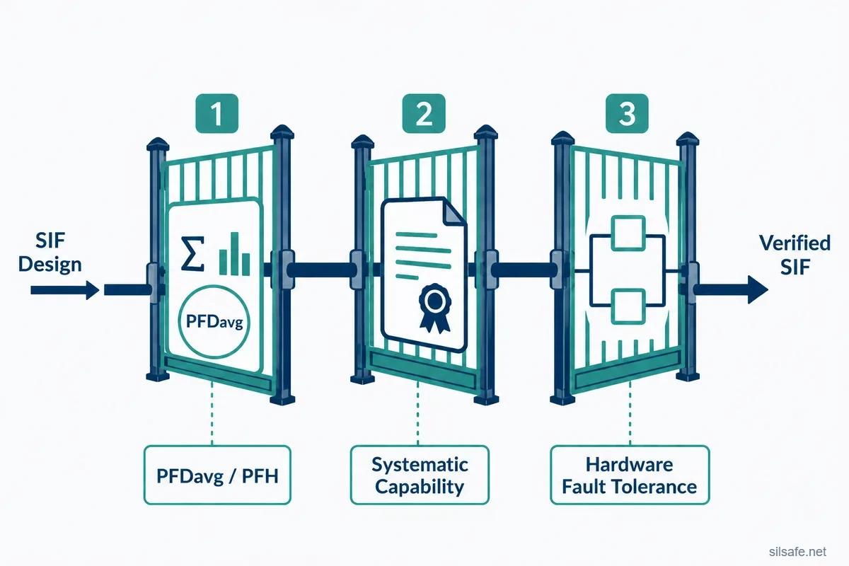
When practitioners say “SIL verification,” they almost always mean one specific process: design-phase verification of a Safety Instrumented Function (SIF) against the three independent requirements in IEC 61511 Clause 11. Three gates, all independent, all of which must pass.
The three gates are:
- PFDavg / PFH — the quantitative gate. The SIF’s failure probability must meet its allocated SIL band.
- Systematic capability — every device in the SIF must be fit for the required SIL, by certification or by prior use.
- Architectural constraints — the SIF’s hardware fault tolerance must be sufficient for its target SIL.
A SIF that nails its PFDavg but fails on systematic capability or architecture is not verified. The gate that gets the most attention, PFDavg, is rarely the one that fails an audit.
A note on terminology before going further. “Verification” in IEC 61511 is broader than what this article covers. It spans the whole life-cycle: H&RA, SRS, design, FAT, operations. “SIL verification” is the industry shorthand for the design-phase SIF verification specifically, and that is what this article covers.
The three worked scenarios at the end show the gates working together: one clean pass and two failure cases that mirror what auditors actually find.
Gate 1: PFDavg / PFH
This is the quantitative gate, defined in IEC 61511 Clause 11.9. The SIF’s calculated probability of failing to act on demand must meet or exceed its allocated SIL band.
Demand mode determines which metric applies. Low demand, where the SIF is called on less than once per year, covers most process industry shutdown SIFs and uses Probability of Failure on Demand average (PFDavg). High demand and continuous mode, more frequent than once per year, cover some compressor protection, fired equipment trips, and machinery safety, and use Probability of Failure per Hour (PFH). High demand and continuous are treated together for SIL verification purposes.
This article is not a PFDavg tutorial. For depth on inputs and methods, see the dedicated PFDavg article in Further Reading.
Why this is the gate everyone fixates on
It produces a number, and numbers feel definitive. Tools automate it. The other two gates require judgment, evidence, and documentation. The PFDavg report is the tangible deliverable a manager can hold up and point to.
The trap is that it’s also the gate easiest to engineer to pass on paper while the SIF still fails on Gates 2 or 3.
Where this gate fails
The PFDavg calculation is only as honest as its inputs and architecture assumptions. The same calculation can produce a false pass or a false fail depending on which way the assumptions lean.
- False pass: optimistic TI, overstated Cpt, generic failure rates that don’t match the real device. The number passes, but real-world risk reduction is lower than the report claims.
- False fail: overly conservative inputs reject a SIF that would actually meet its target. The design ends up over-engineered relative to the real risk.
- Wrong architecture: sometimes the architecture is just wrong for the target SIL. No amount of input tweaking saves a wrong-fit architecture.
Gate 2: Systematic Capability
This gate is about whether the components of the SIF have an applicable level of quality and design rigor for the required SIL. It comes from IEC 61511 Clause 11.5, with the prior use path specifically governed by Clause 11.5.3, and the systematic capability concept itself defined in IEC 61508-2. Systematic capability is a property of the device, not the loop. It addresses systematic faults (design errors, software bugs, manufacturing defects) that redundancy can’t solve.
The systematic capability rating of every device must equal or exceed the SIF’s SIL.
There are two paths to demonstrate it.
IEC 61508 certification (manufacturer-side)
The manufacturer has had the device assessed against IEC 61508 by a certification body. The outcome is a SIL Certificate stating the systematic capability rating, typically expressed as SC 2, SC 3, etc.
Inside IEC 61508, certification can be achieved through different S routes. Route 1S (design-process rigor) is the most common. Route 2S (proven in use) is less common. Route 3S applies to software.
For the facility verifier, what matters is the systematic capability rating on the certificate. The route the manufacturer used to achieve it is documented in the SIL Certificate. Software systematic capability is handled by Route 3S, applied to embedded firmware and application software during certification of devices like logic solvers. For a facility verifier using a certified logic solver, this is captured by the SC rating on the certificate. No separate software analysis required at the facility level.
IEC 61511 prior use (facility-side)
This is IEC 61511’s alternative path when no IEC 61508 certification exists for the device, governed by Clause 11.5.3.
The owner-operator demonstrates suitability through documented field history under similar operating conditions. No certificate of conformance is involved. Prior use is a facility-side justification, not a third-party attestation. The deliverable is a documented prior use file evaluated by the facility’s functional safety engineer and audited by an FSA team.
It requires evidence of:
- Manufacturer quality management
- Device identification and version control
- Performance in similar operating environments
- Sufficient volume of operating experience
Generally a more difficult and document-heavy path than using a certified component.
Terminology traps to watch for
Prior use vs. proven in use. Prior use is the IEC 61511 facility-side path. Proven in use is a specific IEC 61508 route (Route 2S) used by manufacturers seeking certification without a full FMEDA-driven path. Even Goble’s books and many practitioners use “proven in use” loosely to describe both. Be precise in your own documentation.
The H/S route split. The H routes (1H, 2H) belong to architectural constraints (Gate 3). The S routes (1S, 2S, 3S) belong to systematic capability (Gate 2). The H/S split distinguishes what kind of capability is being demonstrated, not which subsystem the route applies to. Practitioners regularly try to apply S routes to Gate 3 or H routes to Gate 2. Keep them separate.
Where this gate fails
- Legacy field devices with no certificate and no defensible prior use file. “We’ve used it for years” claimed without documentation, version control, or operating-condition records is the typical pattern.
- Mismatched systematic capability rating, like using an SC 2 device in a SIL 3 SIF.
Gate 3: Architectural Constraints (Hardware Fault Tolerance)
This gate is about the inherent redundancy of the SIF: does it have enough fault tolerance to survive a single dangerous failure at its required SIL. It comes from IEC 61511 Clause 11.4, with route definitions inherited from IEC 61508-2 Clause 7.4.4.
Hardware fault tolerance (HFT) is the number of dangerous failures a subsystem can tolerate before losing its safety function. A 1oo1 subsystem has no hardware fault tolerance (HFT = 0). A 1oo2 subsystem has HFT = 1.
Two H routes are available, applied per element. Different elements in the same SIF can use different routes.
Route 1H
Route 1H is based on Safe Failure Fraction (SFF) and Type A vs. Type B classification, using IEC 61508-2 Tables 2 and 3. It requires FMEDA-grade failure data to compute SFF.
Type A devices have simple, well-understood failure modes (most mechanical devices). Type B devices are complex with embedded software or microprocessors. The Route 1H tables apply different SFF thresholds to each. Type A is treated more leniently than Type B at the same SIL.
This is the most common route for modern certified components, particularly logic solvers, smart instruments, and modern positioners with documented FMEDAs.
A note on diagnostics. SFF improves when diagnostics catch dangerous failures, but high SFF doesn’t strictly require diagnostics. A device with intrinsically safe failure modes (for example, a spring-return solenoid where loss of power drives the safe state) can hit high SFF with no diagnostics at all. In practice, though, most devices that achieve high SFF on Route 1H do so because of diagnostic coverage.
Route 1H — Type A devices (IEC 61508-2 Table 2)
| SFF | HFT = 0 | HFT = 1 | HFT = 2 |
|---|---|---|---|
| < 60% | SIL 1 | SIL 2 | SIL 3 |
| 60% to < 90% | SIL 2 | SIL 3 | SIL 4 |
| 90% to < 99% | SIL 3 | SIL 4 | SIL 4 |
| ≥ 99% | SIL 3 | SIL 4 | SIL 4 |
Route 1H — Type B devices (IEC 61508-2 Table 3)
| SFF | HFT = 0 | HFT = 1 | HFT = 2 |
|---|---|---|---|
| < 60% | Not allowed | SIL 1 | SIL 2 |
| 60% to < 90% | SIL 1 | SIL 2 | SIL 3 |
| 90% to < 99% | SIL 2 | SIL 3 | SIL 4 |
| ≥ 99% | SIL 3 | SIL 4 | SIL 4 |
Route 2H
Route 2H is based on hardware structural resilience and field reliability data. It does not require SFF and uses simpler tables driven by SIL alone.
This is effectively the route IEC 61511 uses on its own. IEC 61511’s architectural constraint table is derived from IEC 61508 Route 2H, and Goble notes the two are essentially identical.
Route 2H is most common for mechanical devices with no or minimal diagnostics (rack-and-pinion actuators, manual valves), legacy equipment that predates IEC 61508, and any device where FMEDA data is not available.
Prior use data can contribute to other parts of the verification, most directly to Gate 2 systematic capability. The same field history that supports a Route 2H argument for hardware integrity may also support a prior use justification under Clause 11.5.3.
Route 2H — minimum HFT by SIL
| SIL | Minimum HFT |
|---|---|
| 1 | 0 |
| 2 | 1 for high-demand or continuous mode, 0 for low-demand mode |
| 3 | 2 |
| 4 | Special requirements per IEC 61508 |
Choosing an H route
For new SIFs designed with modern equipment, the route appears on the SIL Certificate for certified components, typically labeled “Route 2H Device” or similar. This is the most common situation a facility verifier will encounter.
The decision is per-element and driven by available evidence:
- Devices with FMEDA data and meaningful diagnostics generally go Route 1H.
- Devices without FMEDA data, or mechanical devices where diagnostics can’t catch the dominant failure modes, go Route 2H.
Both routes are legitimate. Route 2H is not a fallback or a downgrade. It is the appropriate route for hardware where the SFF-based approach doesn’t fit, and either route is acceptable evidence for SIL verification at the target SIL.
Where this gate fails
- Claiming Route 1H without the FMEDA data to back it.
- Selecting a 1oo1 architecture for a device whose SFF and Type combination can’t reach the target SIL because of required HFT.
- Using a Route 2H legacy device in a SIL 3 application where Route 2H can’t get there regardless of redundancy.
- Mixing route claims across elements without verifying each element’s evidence stands on its own.
Worked SIL Verification Examples
Three scenarios to make the three-gate framing concrete. Each zooms in on a single component (or two in Scenario 2) within an otherwise-passing SIF. Each scenario opens with a scope statement, then walks through all three gates in whichever order makes the component’s story easiest to follow. These are SIL verification scenario walkthroughs, not PFDavg calculation tutorials.
Scenario 1: A straightforward verification
For this scenario we focus on a smart pressure instrument on a SIL 2 SIF, used in a 1oo1 architecture. Assume the rest of the SIF verifies cleanly.
- Gate 2: The device is IEC 61508 certified, with an SC 2 rating on the SIL Certificate. SC 2 matches the SIF’s required SIL — passes.
- Gate 1: The certificate provides manufacturer failure rate data. This instrument’s contribution to the SIF-level PFDavg, combined with the rest of the SIF’s components, clears the SIL 2 band — passes.
- Gate 3: The SIL Certificate confirms Route 1H, Type B, and a documented SFF of 93% (in the 90% to <99% band). The Route 1H Type B table allows SIL 2 at HFT 0, so the 1oo1 architecture clears — passes.
The rest of the SIF (final element and logic solver) verifies via the same logic. This is what a modern and clean SIL verification looks like: a certified component, a matching SC rating, an architecture that fits the route’s table, and a PFDavg that lands in band.
Scenario 2: A trickier case
For this scenario we focus on two components (a final element and an instrument) on a SIL 2 SIF in low-demand mode. Assume the rest of the SIF verifies cleanly, including the SIF-level PFDavg contribution from other components.
Final element walkthrough, non-certified valve in a 1oo2 architecture:
- Gate 2: Non-certified valve with no IEC 61508 certificate. The facility attempted prior use, but the operating-history records don’t meet Clause 11.5.3 documentation requirements — fails.
- Gate 1: Failure rate data sourced from OREDA for this device class, applied to the SIF-level PFDavg — passes.
- Gate 3: Route 2H requires minimum HFT 0 for SIL 2 in low-demand mode. The 1oo2 architecture provides HFT 1, which exceeds the minimum — passes.
Instrument walkthrough, certified instrument in a 1oo1 architecture:
- Gate 2: The device is IEC 61508 certified with an SC 2 rating — passes.
- Gate 1: Failure rate from the SIL Certificate plugs into the SIF-level PFDavg — passes.
- Gate 3: Type B smart instrument with documented SFF in the 60% to <90% band, in a 1oo1 architecture, is capped at SIL 1 by the Route 1H Type B table — fails.
Two components, two unrelated gate failures, both blocking SIL verification of the SIF as a whole. The final element passes its architecture check but fails systematic capability. The instrument passes systematic capability but fails its architecture check. This is why the gates are treated as independent: a SIF doesn’t get partial credit for clearing two of three on any given component, and clearing all three on most components doesn’t help if one element fails one gate.
Scenario 3: The hardest one to catch
For this scenario we focus on a non-certified globe valve, used in a 1oo1 architecture. Assume the rest of the SIF verifies cleanly.
The engineer specified this valve from a familiar vendor because it was the right size, available, and had been used in non-safety service at the site for years. To populate the verification report, the engineer pulled an SFF figure from the SIL-rated version of the same product family, same vendor, same valve series, but a different model.
- Gate 2: No IEC 61508 certificate for the actual valve installed. The non-safety service history doesn’t qualify for prior use under Clause 11.5.3 — fails.
- Gate 1: PFDavg calculation passes using the borrowed SFF and a generic failure rate from a database — passes.
- Gate 3: Both Route 1H and Route 2H were considered. Route 1H requires FMEDA-grade failure data for the actual device installed. The borrowed SFF from a sibling SIL-rated model doesn’t qualify, and no FMEDA exists for this valve. Route 2H doesn’t require SFF, but does require documented hardware reliability evidence, and the non-safety service history doesn’t meet that bar either — fails.
The rest of the SIF verifies cleanly. One bad component sinks the SIL verification.
The lesson here is that the gates are independent in principle but often connected in practice. A device with no certificate and no defensible field history typically fails on Gate 2 and leaves Gate 3 with no defensible route. And route claims on Gate 3 must be defended with evidence that’s specific to the device installed, not borrowed from a similar product.
Life-cycle Placement
SIL verification sits in the design phase of the IEC 61511 safety life-cycle.
What comes before: H&RA and LOPA produce the SIL allocation for each SIF. The SRS captures the safety requirements. Conceptual SIS design proposes a candidate architecture and equipment selection. SIL verification then takes those inputs and tests them against the three gates.
What comes after: continued detailed design, FAT, installation and commissioning. The verification report is a key input to the Functional Safety Assessment and to operational handover.
Common Mistakes
The mistakes that surface during SIL verification audits are rarely about the math. They are about evidence, judgment, and which gate the engineer treated as optional.
- Treating PFDavg as the only gate. The calculation passes, often using manufacturer numbers without scrutiny, and the audit fails on Gate 2 or Gate 3. This is the most common pattern, and it’s the spine of most of the failures below.
- Claiming prior use without the documentation to defend it. “We’ve run this valve for 15 years” is not a prior use file. Clause 11.5.3 wants quality management, version control, and operating-condition records, not informal recollection.
- Confusing prior use with proven in use, then defending neither correctly when challenged.
- Not realizing a route was claimed at all. Accepting whichever H route the calculation tool defaulted to without checking whether the device’s evidence supports it.
Most of these share a root cause: engineers default to whichever gate they’re most comfortable with and underweight the other two.
Frequently Asked Questions
I thought PFDavg was all we had to do. What’s the deal?
PFDavg is one of three independent gates, not the whole verification. IEC 61511 Clause 11 also requires systematic capability (the device is fit for the SIL by certification or prior use) and architectural constraints (the hardware fault tolerance is sufficient for the SIL). A SIF can have a beautiful PFDavg report and still fail SIL verification. PFDavg gets the attention because it produces a number and tools automate it, but the other two gates are where audits most often turn up problems.
I heard we have to use SIL-certified devices. Is that correct?
Certified devices make your life easier and are recommended, but not strictly required. IEC 61511 also allows prior use as an alternative path under Clause 11.5.3. Prior use is harder and document-heavy. That is the trade-off for skipping certification. Most facilities find the cost of building defensible prior use files component by component exceeds the price premium on certified equipment. SIL Safe defaults to certified components on every project for exactly this reason.
I’ve been using this family of PLCs for years and they’re great. Never had a problem. How can I use this in a SIF?
Possible in theory, expensive in practice, scrutinized at all three gates of SIL verification. On Gate 2, prior use under Clause 11.5.3 needs more than a track record. It needs documented manufacturer quality management, version control, and operating-environment records. On Gate 3, general-purpose PLCs typically lack the diagnostic coverage and architectural features that certified safety PLCs are designed around, so SFF and HFT arguments get hard to defend.
On Gate 1, manufacturer failure rate data is rarely available for non-safety PLCs, and generic database values may not match the actual hardware. The same field history that might support prior use only contributes to the failure rate argument if the facility has safety-grade failure recording, which most general-purpose PLC installations don’t. Add it up and a certified safety PLC almost always wins on total cost.
We just did all this work to use a valve under prior use, and I thought that was it. Now I need to calculate PFDavg too. Where does that data come from?
Prior use clears Gate 2 only. Gate 1 still needs failure rate data to support the PFDavg calculation. For a non-certified valve, that typically means industry databases (OREDA, Exida’s data handbook, or similar) applied to the device class. The data is generally more conservative than what an FMEDA would produce on a certified device, which is one of the practical reasons certified components ease SIL verification across all three gates simultaneously.
Our FuSa engineer says we need 2oo3 voting on this SIF instead of a single instrument, which is going to triple our hardware cost. The PFDavg calculation passes fine on a 1oo1, so why do we need 2oo3?
PFDavg and HFT are independent gates. The PFDavg calculation can pass on a 1oo1 architecture, but Gate 3 is a separate check that the architecture has enough hardware fault tolerance to be trusted at the target SIL. If the instrument’s SFF and Type combination requires HFT ≥ 1 to reach the target SIL per the Route 1H tables, a 1oo1 architecture (HFT 0) is insufficient regardless of what the PFDavg math says.
Two paths through this:
- Pick an instrument with higher SFF (typically smart, fail-safe-designed, or with stronger diagnostics) so 1oo1 clears Gate 3.
- Accept the redundancy.
The expensive smart instrument frequently beats three cheaper instruments plus the wiring, I/O, and proof-testing overhead once total cost is accounted for.
How do we at SIL Safe advise our clients on this topic?
Use IEC 61508-certified components wherever possible. It is the simplest path through all three gates.
Gate 1 is easier because the manufacturer provides failure rate data, and that data is typically less conservative than generic database values for the same equipment type. The FMEDA process produces a component-specific number rather than a worst-case estimate across a heterogeneous population.
Gate 2 collapses to a check that the SC rating matches the SIL.
Gate 3 collapses to a check of the architecture against what the certificate documents (route, SFF where applicable, and Type). SFF on certified components tends to be relatively high because the FMEDA process and the certification market push toward devices with strong diagnostics, which makes the table lookup more likely to clear at the target SIL.
Does the standard clearly state these three gates in those exact terms?
No. The three-gate framing for SIL verification is shorthand extracted from various clauses (11.4, 11.5, 11.9). The standard treats the requirements as separate within the design phase. The framing is a teaching device, not a quoted structure.
Further Reading
From SIL Safe
- Layer of Protection Analysis (LOPA): The Engineer’s Guide to SIL Selection
- Hazard and Risk Analysis Methods: How HAZOP, What-If, LOPA, Risk Graph, FTA, ETA, and Bowtie Fit Together
- PFDavg Explained: 6 Essentials for Getting Started with SIL Calculations
- Functional Safety Assessment (FSA) vs. Audit: What’s the Difference?
External resources
- IEC 61511-1:2016+A1:2017 — official IEC publication page
- HSE — Functional safety (BS EN 61511 reference page)
- ISA-84 Series of Standards
- The 61508 Association — Proven in Use technical guide
Closing Synthesis
SIL verification is three independent gates, all of which must pass. Most failures come from underweighting two of the three, usually because the third produces a clean number on a report. Treat them as separate checks, defend each one with its own evidence, and the verification holds up under audit.
Functional safety is complex, and the stakes are high. If you have questions about your SIS design, SIL verification, or where to start with IEC 61511, the team at SIL Safe is here to help. Reach out to us today.